Failure in Multimedia Filters
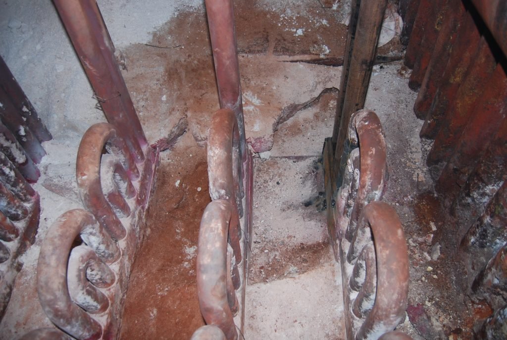
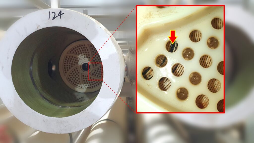
This article dives into a case where a small defect in a multimedia filter had major consequences, affecting the integrity of reverse osmosis membranes and highlighting the importance of having a robust and reliable design. The photo above was taken from the inlet of a reverse osmosis (RO) pressure vessel, where you can see a […]
Failure in Multimedia Filters Read More »