Forensic Engineering

A Few Corrections To Avoid Hideout Effects

A Few Corrections To Avoid Hideout Effects

Problem Experienced

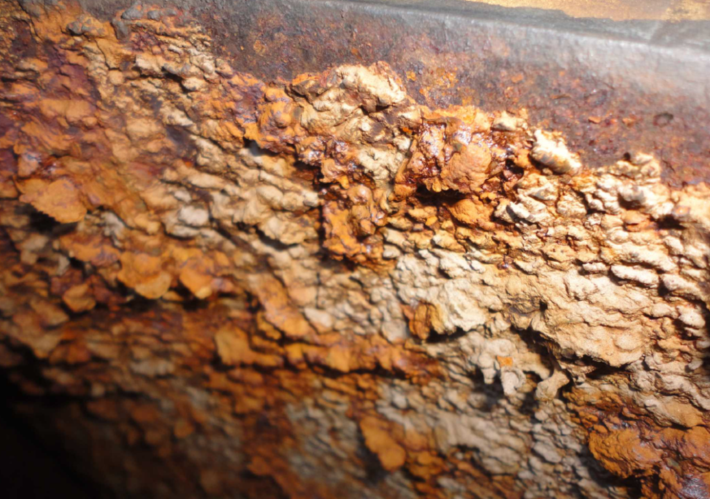
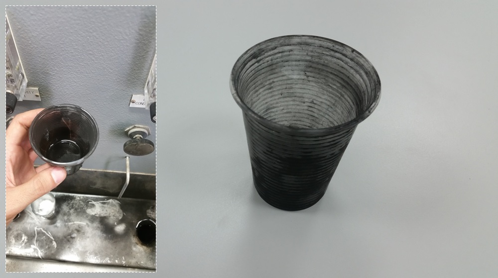
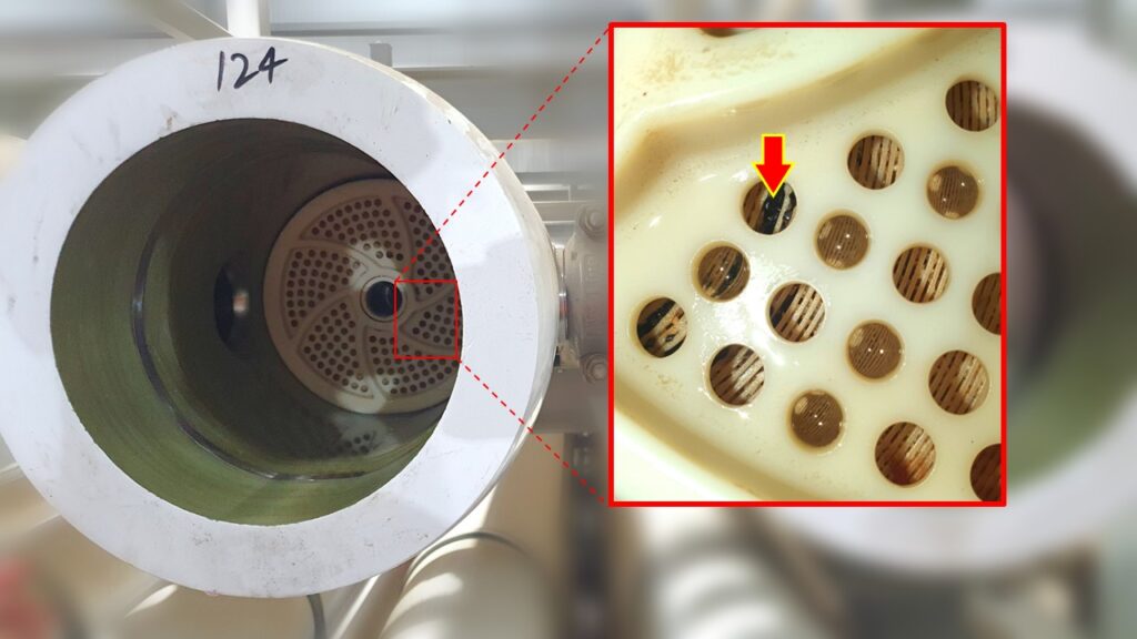
The phenomenon of scaling is a type of fouling typically observed in heat exchangers, steam generators and cooling systems. It is caused by the interaction of chemical species dissolved in the water to form inorganic salts.

The most common species which bring about the formation of scales are calcium and sodium-based compounds. The solubility of theses salts is temperature and pH dependent and it is somewhat sensitive to possible variations. In some cases, they can present several points of low solubility and create hideout effects in transitory conditions.

That is the case we have recently observed in a power plant due to phosphate hideouts which was noticed during the daily startup. Phosphate hideout is the result of chemical reactions of sodium phosphate with iron oxides where the reaction products has low solubility in high operating conditions.  As consequence, salt precipitation occurs. However, at lower loads and heat fluxes, these precipitates will undergo hydrolysis and return to solution. If the problem is not properly identified, these scales of phosphates can lead to various issues which are mainly loss of pressure drop, resistance to heat transfer and erosion-corrosion.

Technical Approach

We were able to solve the problem by implementing a few corrections based on the following approach:

  • In an attempt to control the effects of phosphate hideouts and scale formations, it was required to perform some changes the chemical treatment program. The first approach was to dose a mixture of tri-sodium and di-sodium phosphate which reduces the amount of sodium and therefore, minimizes the risk of carryovers. Another possibility that was tested required the dosing of Trisodum Phosphate which helps to control any possible acid attack. But it was difficult to maintain the equilibrium. Given the nature of the process conditions, we decided to go with All Volatile Treatment.
  • An optimization of the hydraulic of the system was necessary to enhance fluid velocities and flow distribution. These parameters has a direct influence in the rate of deposition; therefore, this analysis gave as the possibility to create a map of zone with high probability of accumulation of scales.
  • High Reynolds numbers must be achieved by installing of swirling devices. This ensured the correct grade of turbulences and the right chemical mixing during dosing. In addition, some of the dosing points where changed to a more appropriate location.
  • Solubility and reactivity of chemical compounds is primary governed by temperature, so it is necessary to consider this relation when choosing the right chemistry which must be suitable to the process.
  • Another factor is the material selection which is the core value for a passive protection and corrosion resistance of the system. Some of the points with severe grade of corrosion, where replaced by high grade steels and stellite coating.
Forensic Engineering

Cooling Towers Blowdown Systems

Cooling Towers Blowdowns

Problem Experienced

In cooling towers, the heat is rejected by the partial evaporation of water as it flows through the unit. The evaporation will bring along a rapid concentration of the chemical species naturally dissolved in the water.

The principal scale found in cooling towers is calcium carbonate which comes from the decomposition of calcium bicarbonate. This process of decomposition may also form derivative salts with magnesium, sodium or silica among others. Whichever may be the case, their solubility would depend on conductivity, hardness, pH and temperature.

Given no control, the increase of salts concentration can compromise the integrity of the system and reduce its efficiency. In a more extended scenario, scales formed in the cooling tower can travel all the way to the condenser, create hard deposition and affect the steam condensation process. If the cooling system fails to drop down the temperature in the condenser, then the vacuum will decrease and interfere in the overall efficiency of the plant.

Tackling the problem

The problem can be tackled by applying an adequate chemical treatment program, but also it is required the design of an effective blowdown system. In fact, the operation of a cooling tower is measured by the “cycles of concentration”. This ratio is determined by comparing the concentration of dissolved solids between the blowdown and the makeup water. The optimization of this ratio will reduce the scale buildup potential, decrease the water consumption and limit the blowdown disposal.

The monitoring and control of the blowdown quality and flow is essential to ensure the correct operation of the cooling tower. The logic control loop can be implemented by mean of a control valve linked to a conductivity meter. The conductivity controller will automatically trigger the blowdown valve to keep the level of concentration as close as possible to the setpoint.  The setpoint would depend on the material specifications of the cooling tower and the chemical treatment program used for operation.

In most cases, low pH is also required to keep solubility below the saturation point. Acid treatments change the equilibrium of carbonates toward the formation of more soluble compounds. This way the setpoint of conductivity can be increased to operate at higher cycles of concentration and prevent the deposition of salts.

The below image shows the effect of lack of balance in the blowdown, and also it was aggravated by deficiencies in the chemistry control of the system. The problem was specifically due to high levels of chloride and conductivity.

Commissioning

Commissioning Failures VS Plant Performance

Commissioning & Plant Performance

Abstract

Failures in the execution of commissioning activities, like chemical cleaning or steam blowing, can go unseen for the first several months of operation, but they have the potential cause a direct impact in the performance of a power plant.

This article presents the problems experienced in a CSP Solar Power Plant, due to damages in the regeneration system, and how they dragged down the productivity of the plant.

Performance & Regeneration

Solar power plants operate on the principles of fluid mechanic and thermodynamic. The core value of any system design is the mass & heat balance, which subsequently stands as the building blocks of the performance model.

The performance model is conceived to identify the most significant aspects of the way in which a solar plant operates under ideal conditions. The results are used as a reference for running the plant as close as possible to that theoretical model. Along this line, we can identify divergencies, understand the way a solar plant functions and enhance the overall efficiency of the plant.

The overall efficiency depends on the performance of each individual system, and in this regard, regeneration plays an important role. The idea behind regeneration is to increase the thermal efficiency of the plant by raising the feedwater temperature before it enters the Solar Steam Generator (SSG). The process is accomplished in the so-called feedwater heaters where water is heated with bleed steam extracted from different stages of the turbine at given thermal conditions.

Regeneration decreases the thermal input required, reduces the gradient of enthalpy in the SSG, minimizes the risk of thermal shock in the preheater and increases the overall efficiency. Therefore, any possible departure from the expected operation of the regeneration system, will directly drag down the productivity of the plant.

That was the case experienced in a CCP solar power plant due to severe failure in the feedwater heaters during commissioning.

Process Description

The design of the plant incorporates parabolic through technology to capture solar energy in a heat transfer fluid (HTF). The HTF is sent to the solar steam generator (SSG) to exchange its enthalpy with high quality water to produce superheated steam. The process is carried out in a counter-current flow scheme, so hot oil produces superheated steam, then boils the water in the evaporators and finally, preheats the water in the economizer unit. The efficiency of the heat transfer depends on the water inlet temperature at this point of the system.

Eventually, the superheated steam is admitted to a steam turbine which exhausts the load to a surface condenser. The hotwell section serves as a water reservoir from where the condensate is pumped back to the cycle.

Now is when Regeneration takes place. A battery of heat exchangers set in a cascade configuration, are employed to rise the temperature of the water up to the steam generator economizer inlet. As depicted in figure 1, H3 and H4 are low pressure heat exchangers whereas H1 and H2 are designed for high-pressure. All of them are shell-tube type. Water flows through the tube side of the unit, while bleed steam is condensing in the shell side (black dash line). DA represents the deaerator, which is a direct mixing exchanger designed for removal of oxygen, CO2 and volatile impurities.

Failures in the Regeneration System

Operating anomalies were observed in the functionality of the feedwater heaters H1 and H2 throughout the first months of operation. A gradual decrease in their thermal performance brought the appearance of collateral problems which ended up affecting the total efficiency of the cycle. Therefore, a failure investigation was conducted to find out the root-cause of the problem and implement corrective actions to improve its performance.

The results of the analysis determined that these heaters got affected during the commissioning of the project. Both units were included in the scope of chemical cleaning and initial flushing, though, poor actions were taken to preserve their integrity during the execution of the activities. As a result, the second heater H2 acted as a real filter and a great deal of metal debris got blocked in most of the tubes. In view of the severe damage and leakages, this unit had to be replaced one year later.

Image 1 shows the frontal tube sheet of the second feedwater heater (H2). There were found uncountable numbers of eroded fragments of metals, welding slags, and stones embedded in the tubes. More than 55% of the tube bundle got permanently clogged.

The problem was detected due to a significant overconsumption in the feedwater pumps. Friction losses through the heaters may cause restriction of the water flow, and pumps need to increase speed to overcome the pressure drop. This could bring pumps to run beyond the allowable operating range which intensely reduces their efficiency. In a more extreme scenario, if the situation persists, the temperature reached in the pump could bring the water to its boiling point and cause more serious problems like cavitation, vibrations or mechanical failures in the rotating components.

The presence of metal debris in the heaters and the material incompatibility with the tubes favored the appearance of several types of corrosion attack. Subsequently, some them started to leak. Since pressure in the water side is around 80-100 bars greater than in the steam side, the mass of water passing to the shell side was enough to reduce the temperature of steam several degrees. This made the heat transfer not only less effective but also reduced the pressure in the deaerator. As a consequence, the quality of the water may be affected.

In any case, all of these instabilities forced opening the H2 manual bypass and leaving the heater out of service.

Bypassing H2 implied a temperature drop of 25ºC on average at the preheater inlet. The loss of enthalpy can be compensated by putting in solar tracking additional CCP mirrors. This action will concentrate more energy and increase the flow of HTF.

However, the problem went unseen for the first months of operation because, as it pertains to the process design, heaters H1 and H2 would remain out of service or in intermittent operation during summer operating mode. Thus, the 1st and 2nd extractions would be closed for the turbine to gain an extra flow of steam, and so, increase the production in 5% of the nominal gross. During winter, the maximum yield of the plant is achieved by using the total solar field, therefore, there would not be additional availability of solar field to mitigate the fall of temperature in the water side. So, the plant was forced to accept a loss of efficiency.

The problem in the feedwater heaters brought one further issue which also affected the performance of the plant which is depicted in Figure 3. Since the preheater inlet temperature is lower, and there is not extra heat input from the turbine extractions, the SSG would take longer to achieve its operating nominal point during the daily startup. By the same token, there was a loss of intertia on daily shutdown.

Conclusions

Commissioning is likely the most critical stage in the life time of a power plant due to the transient conditions which systems and equipment are exposed to. The total efficiency of the plant depends on the functionality of all of them.

Thus, any failure in design and execution of field activities have the potential to damage critical equipment and cause deviations in their expected performance. This may represent a significant impact in the overall performance of the plant. Therefore, it is advised to carry out continuous inspections, comprehensive monitoring of each system during the start-up of the plant, especially, develop Hazard and Operability Analysis plan for critical commissioning activities.

Refer to the following post to find extra information about this type of failure, click here

Forensic Engineering

Chemical Corrosion Damage in Adiabatic Expansions

Corrosion Damage in Expansions

Description

A sudden change in a fluid cross-section area provokes a dynamic condition in which water pressure drops sharply below its boiling point and produces instant vaporization.

Since this process is adiabatic, there is no exchange of heat with its surroundings, therefore, the total enthalpy remains the same. Consequently, most of the water molecules will absorb the bulk of that energy as latent heat and will make water turn into steam.

This phenomenon brings about many destructive effects related to chemical corrosion attack, which is one of the most common issues found in steam water systems. Subsequently, it can derive to accumulation of sediment in the cycle, under-deposit corrosion, overheating, caustic corrosion, control valve obstructions or spray nozzle cloggins to mention a few cases.

The problem is likely encountered in LP drain motorized valves feeding flash tanks, spray nozzles and diffusers at bypass attemperations, orifice plates, nozzle or pitot flowmeters, LP flash tank drains to condenser, blowdown systems. We have also observed the same type of corrosion patterns at the deaerator nozzles.

Image 1 represents the cross section top view of a HRSG preheater module It also shows how temperatures vary at the back-end tubes. The increase of velocity in the flue gas would produce gradients of pressure between the two opposite sides of the tube. In consequence, this would eventually create a vortex effect and turbulences in the backside of the tubes. This is shown in image 2.

Turbulence would drop velocity down to zero near the surface, which would decrease the rate of energy transfer from the flue gas to the condensate. By the same token, the lack of flue gas circulation around the tubes would bring temperatures down below the dew point and end up creating droplets of condensation. Image 3 shows areas of high probability for this phenomenon to occur. In that event, a layer of condensation would develop all along the surface of the tubes, while drastically altering the heat convection and thermal conduction rate across the wall.

Chemical Corrosion Issues

It is empirically proven that solubility of chemical species is actively dependent on pressure and temperature, among other properties. Although there is not a direct correlation to predict such dependency, it has been observed that, for most compounds, solubility falls with a decrease in those properties.

As water expands into a pressure below the boiling point, some impurities will exceed its limit of saturation and precipitate. In fact, these precipitates are deposits of salt compounds which can be very aggressive to the equipment. Depending on the nature of the accumulation, the affected zone can develop several types of corrosion patterns. Hence, sodium salts can undergo hydrolysis and produce caustic corrosion. Silica precipitates to form a very hard and impervious scale which can derivates into stress corrosion cracking. Sodium carbonate or sodium chloride can be adsorbed on the surface of the metal affecting the passivation protective layer. Under-deposit corrosion would be expected to happen in most of cases as a result of electrochemical reactions underneath deposition of salts.

I took the attached photo during a inspection to show calcium carbonate deposits (light white patterns) encountered downstream the HP spray attemperation bypass valve.

Air in-leakage in the condenser, caused high level of carbon dioxide dissolved in water, in the form of carbonic acid ions. Subsequently, the carbonic acid ions combined with impurities of calcium dissociated in water to form calcium carbonate. In the even of an abrupt expansion, which is the case of the spray attemperation, the equilibrium among the chemical species dissolved in water is broken. Some ions will vaporize and escape as carryovers into the steam flow, while other impurities will exceed its solubility under the given conditions and precipitate as insoluble salts.

Refer to the following post to find extra information about this type of failure, click here

Engineering

HRSG Preheater Simulation

HRSG Preheater Simulation

Purpose

A computational fluid dynamic simulation was carried out to study the effects of the flue gases velocity in the last stage modules of a HRSG preheater. The results allows us to visualize a map of temperature in a preheater module, hence, to better understand how energy is distributed. In addition, it provides valuable information to predict points of low efficiency and propose estrategies for optimization.

Description

Image 1 represents the cross section top view of a HRSG preheater module It also shows how temperatures vary at the back-end tubes. The increase of velocity in the flue gas would produce gradients of pressure between the two opposite sides of the tube. In consequence, this would eventually create a vortex effect and turbulences in the backside of the tubes. This is shown in image 2.

Turbulence would drop velocity down to zero near the surface, which would decrease the rate of energy transfer from the flue gas to the condensate. By the same token, the lack of flue gas circulation around the tubes would bring temperatures down below the dew point and end up creating droplets of condensation. Image 3 shows areas of high probability for this phenomenon to occur. In that event, a layer of condensation would develop all along the surface of the tubes, while drastically altering the heat convection and thermal conduction rate across the wall.

Why is that relevant?

Back-end corrosion occurs when the gas turbine’s exhaust temperature falls below the dew point of any combustion product. Subsequently, high corrosive liquid acid would form in the presence of moisture. When natural gas contains sulfur in its composition, the reaction products derived from combustion will have, in addition to carbon dioxide and water, an equivalent proportion of sulfur dioxide. This compound will oxidize to sulfur trioxide and create sulfuric gas as it combines with the humidity of the flue gas.

If the temperature of the flue gas falls below the dew point of the sulfuric gas, liquid acid will form on the surface of such regions.

The aggressiveness of this attack depends on the concentration of acid in the condensate, which depends on the equilibrium H2O – H2SO4.

This simulation allows us to predict points of high probability where condensation droplets might form in the preheater module, so satisfactory mitigation strategies can be implemented during the HRSG design.

Refer to the following post to find extra information about this type of failure, click here

Commissioning

Ineffective Cleaning?

Ineffective Chemical Cleaning?

Introduction

Ineffective chemical cleaning? Not really… we have encountered situations where engineers and operators complaint about the cleanliness of the boiler as they see a black liquid coming off the blowdown system during first fire.

It´s not difficult to get carried away by a first impression and put into question the effectiveness of the chemical cleaning.

Explanations

This dark watery constituent is in reality a very welcome natural corrosion-protection product called Magnetite and it is formed as the steel surface is exposed to water under certain conditions.

The formation of Magnetite is an electrochemical process controlled by a continuous diffusion of iron ions from the steel surface across the water boundary layer and its stability, morphology and porosity depends on the oxidation-reduction potential, pH, oxygen concentration, pressure, temperature and the influence of the make-up water chemistry (CO2, Cl, Si, Na, Ca, Mg…)

Solubility rises with temperature up to 150ºC, then decreases with a steep drop to 300°C. Pressure promotes the growth of magnetite and thickness Having said that, the reason of the dark appearance of the blowdown during a boiler ramp-up is mainly due to the deposition of low quality magnetite since steady conditions has not been reached yet.

magnetite